In the previous part, we established an on-premises identity foundation. The on-premises setup consists of a virtual network with Windows and Linux VMs joined to an on-premises Active Directory domain hosted on two domain controllers. In this part, we will create a VPN Gateway in Azure and a StrongSwan IPsec gateway on-premises and establish the Site-to-Site VPN tunnel — the foundation of our hybrid lab.
Implementing a Site-to-Site (S2S) tunnel is simple — so rather than walking through the steps procedurally, I want to focus on what each component is actually doing.
A Site-to-Site VPN connects two networks over the public internet using an encrypted IPsec tunnel. Each end has a gateway that authenticates the other using a Pre-Shared Key (PSK). Only traffic destined for the remote subnet goes through the tunnel — everything else uses the normal internet route. The tunnel is managed by IKE (Internet Key Exchange) which negotiates the Security Association (SA) — the agreed encryption parameters — before any traffic flows.
Before walking through the steps, here are the key addresses we’ll reference throughout
192.168.122.0/24— On-prem network hosting KVM VMs (virbr0)192.168.1.106— on-premises VPN gateway (Strongswan)192.168.1.0/24— on-premises Wi-Fi LAN61.69.136.49— On-premises public IP20.219.67.227— Azure VPN Gateway Public IP10.66.0.0/16— Azure VNet10.66.0.0/24— Azure GatewaySubnet10.66.5.0/24— Azure WorkloadSubnet
Some of these will be created in the steps below; others are already in place from earlier parts.
Azure Configurations
1. Create a virtual network in Azure
While creating a vnet using Azure portal, decide on an address range and create two subnets named GatewaySubnet and WorkloadSubnet as show below. In WorkloadSubnet we will create VMs that want to talk to on-premises.
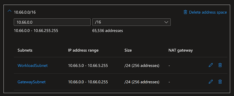
Once the VNet is provisioned, we need three components at Azure end that enable the connectivity with on-premises — a VPN gateway, a Local Network Gateway and a link between these two components
2. Azure VPN Gateway
This is the component that is responsible for establishing a secure tunnel with the on-premises. VPN Gateway is deployed in the virtual network you have chosen to pair with your on-premises network and has to be deployed in GatewaySubnet only — this is a hard requirement. Azure reserves this subnet name specifically for gateway infrastructure and rejects deployment attempts to any other subnet name. All traffic comes in and goes out via this VPN Gateway if force tunneling is enabled. Incoming traffic lands in the GatewaySubnet and from there it will be routed to the destination within the VNet.
For our purpose, a Basic tier VPN gateway would suffice. The Azure portal no longer shows a VPN type selector — all new gateways are route-based by default which support IKEv2. This is what we will use.
Remember that on top of fixed monthly charge, there are costs associated with traffic entering and leaving the network via VPN Gateway — https://azure.microsoft.com/en-us/pricing/details/vpn-gateway/
Once the VPN Gateway is created, take a note of the public IP assigned to it. In my case it is — 20.219.67.227
3. Local Network Gateway
Now that we have a gateway in our Azure VNet, we need a way to identify the on-premises network. For this, an Azure service called Local Network Gateway is used. This is the representation of on-premises network. When you create a Local Network Gateway provide the static IP of your on-premises as the IP address and the network ranges that you want to include in the tunnel as address ranges —
IP address — 61.69.136.49 (public IP of your Wi-Fi router), you can confirm this by running the below command
curl -s ifconfig.me # 61.69.136.49
Note: This address can change when your ISP reassigns it, which typically happens on router restart or DHCP lease expiry. For home lab, this is fine but if you are having a serious setup you must consider getting static IP for yourself.
Address Space(s) —
**192.168.122.0/24** (the libvirt virtual network) &**192.168.1.0/24** (your Wi-Fi network)
Note: You can skip the Wi-Fi range if you do not intend to have other devices in your Wi-Fi to participate in the S2S tunnel
4. Connection
And the final bit of the Azure end of configuration is a Connection. A connection is the link between the VPN Gateway and the Local Network Gateway.
From VPN Gateway, create a connection of type “Site-to-Site (IPSec)” and choose IKEv2, provide the shared key (PSK), connection mode and leave the rest as it is.
On-premises configuration
On-premises needs VPN Gateway configurations similar to the Azure site. The on-premises configuration is simpler by comparison. We will use StrongSwan as the VPN Gateway and the following sections walk through the necessary configurations to enable a site-to-site tunnel
5. Install / Configure StrongSwan
StrongSwan is an open-source IPsec implementation for Linux. It runs as a daemon on the on-premises host and is responsible for IKE negotiation, SA establishment, and installing the resulting XFRM policies and keys into the Linux kernel.
Install StrongSwan and ensure it is running
sudo apt install strongswan
sudo systemctl enable strongswan-starter
sudo systemctl start strongswan-starter
sudo systemctl status strongswan-starter
6. ipsec.conf
This is StrongSwan’s main configuration file — it defines the tunnel connection parameters including peer identities, the subnets to advertise on each side, the encryption proposals, and the connection behaviour on startup and failure.
sudo nano /etc/ipsec.conf
Minimal config:
config setup
    charondebug="ike 2, knl 2, cfg 2"

conn azure-s2s
    keyexchange=ikev2
    left=<onprem\_vpn\_gateway\> #Linux box with Strongswan
    leftid=<onprem\_vpn\_gateway\> #Linux box with Strongswan
    leftsubnet=<onprem\_subnet\_1\_range\>,<onprem\_subnet\_2\_range\>
    right=<azure\_vpn\_gateway\_public\_ip\>
    rightid=<azure\_vpn\_gateway\_public\_ip\>
    rightsubnet=<azure\_workload\_subnet\_address\_range\>
    authby=secret
    auto=start
    ike=aes256-sha256-modp1024! (acceptable for lab environments)
    esp=aes256-sha256!
    dpdaction=restart
    dpddelay=30s
    dpdtimeout=120s
Each attribute controls a specific aspect of how StrongSwan negotiates and maintains the tunnel:
**keyexchange=ikev2** — specifies IKEv2 as the key exchange protocol. IKEv2 is more efficient than IKEv1 (fewer round trips to establish the SA) and handles NAT traversal natively, which matters here since the on-premises side is behind a home router.
**left** / **leftid** — identifies the local end of the tunnel. left is the IP StrongSwan binds to; leftid is how it identifies itself to the remote peer during IKE negotiation. Both are set to the StrongSwan host’s LAN IP here.
**leftsubnet** — defines what on-premises ranges StrongSwan advertises through the tunnel. These must match the address spaces configured in the Azure Local Network Gateway — Azure uses the LNG configuration to inject routes into the VNet.
**right** / **rightid** — the mirror of left, identifying the remote peer — in this case the Azure VPN Gateway’s public IP.
**rightsubnet** — the network ranges behind the Azure VPN Gateway that on-premises should route through the tunnel. Traffic destined for these ranges will be intercepted by XFRM and encrypted.
**authby=secret** — use a Pre-Shared Key for authentication, as configured in ipsec.secrets.
**auto=start** — bring the tunnel up automatically when StrongSwan starts. Setting this to add instead would make StrongSwan a passive responder only.
**ike=aes256-sha256-modp1024!** — the Phase 1 (IKE SA) proposal: AES-256 encryption, SHA-256 integrity, and Diffie-Hellman group 2 (modp1024 — acceptable for lab environments). The trailing ! means this is the only proposal offered — StrongSwan will not fall back to weaker algorithms. Azure must match this exactly.
**esp=aes256-sha256!** — the Phase 2 (ESP) proposal governing how actual data packets are encrypted inside the tunnel. Same strict-match semantics as the ike line.
**dpdaction=restart** — Dead Peer Detection behaviour. If the remote peer goes silent, StrongSwan will attempt to re-establish the tunnel rather than leave a stale SA. dpddelay and dpdtimeout control how long it waits before declaring the peer dead.
Example —
config setup
 charondebug\="ike 2, knl 2, cfg 2"

conn azure\-s2s\-manual
 keyexchange\=ikev2
 left\=192.168.1.106
 leftid\=192.168.1.106
 leftsubnet\=192.168.122.0/24,192.168.1.0/24
 right\=20.219.67.227 # (hce\-d01\-vpngw\-pip)
 rightid\=20.219.67.227 # (hce\-d01\-vpngw\-pip)
 rightsubnet\=10.66.5.0/24
 authby\=secret
 auto\=start
 ike\=aes256\-sha256\-modp1024!
 esp\=aes256\-sha256!
 dpdaction\=restart
 dpddelay\=30s
 dpdtimeout\=120s
**_rightsubnet_**= where your workloads live = what you want to reach.
GatewaySubnetis infrastructure — it’s where Azure’s VPN Gateway itself runs. You never deploy VMs there, and you never put it inrightsubnet. It’s not a destination, it’s a transit point.
So the mental model:
rightsubnet = subnets behind the remote gateway
= where the actual VMs/services are
= NOT the gateway’s own subnet
Same logic applies symmetrically to
leftsubneton your side — it’s the subnets behind your StrongSwan (your VM network, your LAN), not StrongSwan’s own IP.
The gateway subnet on both sides is implied — both ends know the gateways exist because they’re talking to each other. What they need to tell each other is “what’s behind me that you can reach.”
7. ipsec.secrets
The ipsec.secrets file is read by Charon — StrongSwan’s IKEv2 keying daemon — at startup and on ipsec reload. It holds the Pre-Shared Key used to authenticate both peers during IKE Phase 1. The format is:
<local-id\> <remote-id\> : PSK "shared-secret"
The two IPs identify the tunnel endpoints — they must match the leftid and rightid values in ipsec.conf exactly, because charon looks up the secret by matching the peer identities presented during IKE negotiation. The PSK itself must match what was configured in the Azure Connection resource, character for character.
This file does not change structure over the lifetime of the tunnel. The only reason to update it is if you rotate the PSK — in Azure you set a new shared key on the Connection, then update the value here and run sudo ipsec reload secrets to pick it up without restarting the daemon or dropping the tunnel.
One important operational note: this file contains a plaintext secret and should be owned by root with permissions 600. StrongSwan will warn if it is world-readable.
sudo nano /etc/ipsec.secrets

192.168.1.106 20.219.67.227 : PSK "your\_shared\_key"
We have setup all necessary infrastructure to bring up the tunnel now. But before that, let us understand a bit about how tunnels are established
Under the Hood: The Mechanics of Tunnel Initiation
The S2S tunnel was initiated from on-premises —
When StrongSwan sends the initial IKE packet outbound (src: 192.168.1.106:500 → dst: 20.219.67.227:500), the Wi-Fi router performs source NAT — replacing 192.168.1.106 with the public IP 61.69.136.49 — and records this translation in its conntrack table. When Azure replies, the router matches the inbound packet against that entry and reverses the translation, forwarding the packet to 192.168.1.106.
The S2S tunnel is initiated from Azure —
in this scenario, the Azure VPN Gateway is the initiator of the tunnel. This will fail to even establish a tunnel unless a port-forwarding is configured on the Wi-Fi router. If you are curious, here are the steps to have Azure initiate the tunnel.
1. Set auto=add in ipsec.conf — tells StrongSwan that it should not initiate tunnel and just be a responder, StrongSwan won’t initiate the tunnel on startup and won’t re-initiate if it drops.
2. Set Connection Mode to InitiatorOnly in Azure Local Network Gateway » Connection » [Your Connection] » Configuration blade properties.
3. Enable port forwarding in your Wi-Fi router with these values 1. InternalIP:192.168.1.106 — InternalPort:500 — Protocol:UDP — ExternalPort:500 2. InternalIP:192.168.1.106 — InternalPort:4500 — Protocol:UDP — ExternalPort:4500
Port 500 is used for the initial IKE handshake. Port 4500 is used for NAT Traversal (NAT-T) — once both sides detect a NAT device on the path, all subsequent IKE and ESP traffic moves to UDP:4500.
These rules tell the Wi-Fi router to forward any inbound UDP:500 and UDP:4500 traffic arriving on the WAN interface to 192.168.1.106, regardless of the source. Without these rules, the router has no NAT mapping for unsolicited inbound IKE packets and drops them.
IMPORTANT — Who initiates the tunnel has no bearing on data packet routing between the sites as long as the tunnel is UP. Once the IPsec SA is established, the tunnel is a symmetric pipe — packets flow freely in both directions regardless of which side initiated IKE. Once the tunnel is up, the success and failure points are identical in both cases.
Bring the tunnel up
With both sides configured, bring the tunnel up from the StrongSwan host. Follow the below steps to bring the tunnel up.
# Check current state
sysctl net.ipv4.ip\_forward

# Enable if 0
sudo sysctl -w net.ipv4.ip\_forward=1

> ip\_forward must be enabled for the StrongSwan host to forward packets between interfaces — we will cover exactly why in Part 6.

#Start strongswan - if is just installed or not running else run ipsec restart and skip the second step
sudo ipsec start

#Bring connection up
sudo ipsec up azure-s2s-manual

#Verify
sudo ipsec status

`ipsec status` output should show the tunnel as `ESTABLISHED`

Security Associations (1 up, 0 connecting):
azure-s2s-manual\[1\]: ESTABLISHED 13 minutes ago, 192.168.1.106\[192.168.1.106\]...20.219.67.227\[20.219.67.227\]
azure-s2s-manual{1}:  INSTALLED, TUNNEL, reqid 1, ESP in UDP SPIs: c0a6aaf5\_i 90cbbb64\_o
azure-s2s-manual{1}:   192.168.1.0/24 192.168.122.0/24 === 10.66.5.0/24
Summary
Now that the tunnel is established, it’s worth mapping out the traffic flows it enables — and one it doesn’t, yet. There are 3 scenarios of bi-directional traffic flow in our setup between —
- Azure Virtual Machines and On-premises Virtual Machines
- Azure Virtual Machines and On-premises VPN Gateway
- On-premises VPN Gateway and the On-premises Virtual Machines
Except the packet flow from Azure virtual machine destined for on-premises KVM virtual machines (which sit behind StrongSwan on the libvirt network), all of the above will work without any additional configuration.
In the next part of the series we will discuss why they work and why one of them doesn’t.